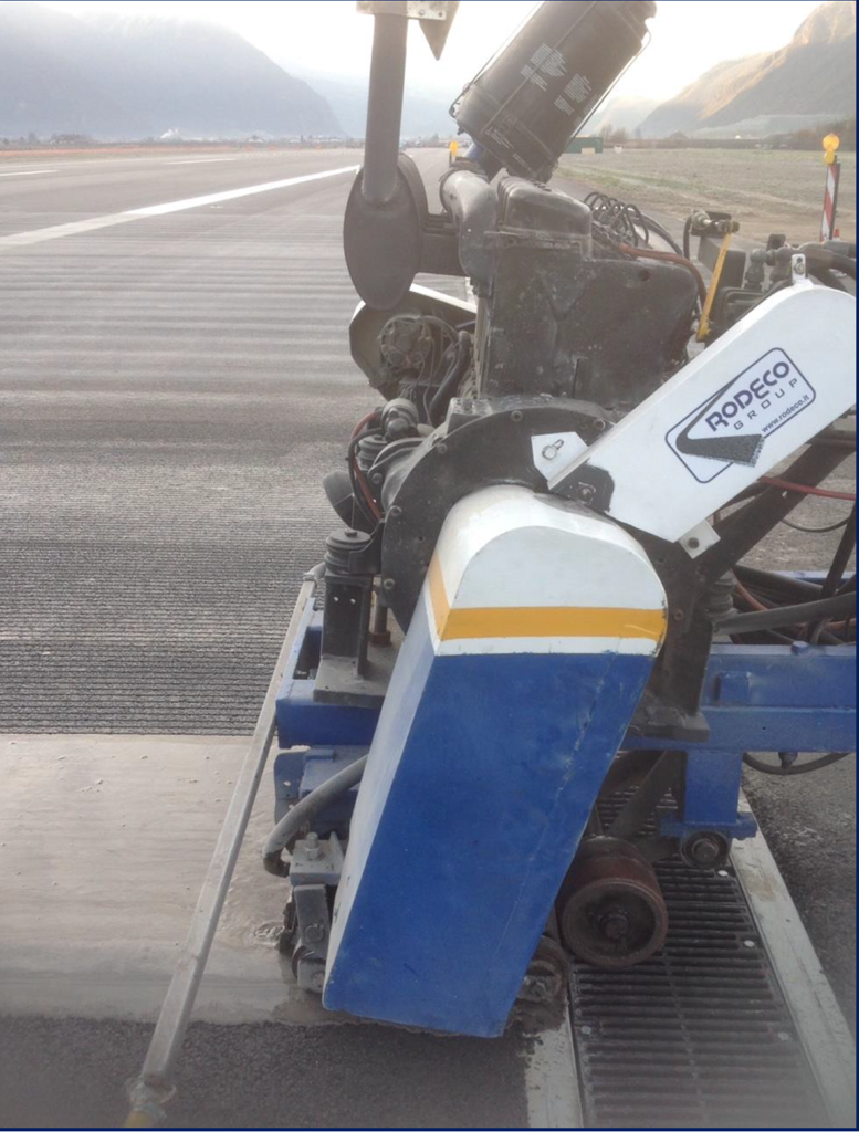
Grooving is a technique of sawing the pavements, especially the runway, in order to improve the surface conditions in rainy conditions and stagnant water, in terms of adherence and prevention to aquaplaning. This technique can be applied both on flexible and rigid pavements, and on newly built or existing, as maintenance to be considered a priority. Grooving mainly provides forced water escape from the pavement surface under aircraft tires traveling at high speed.
The main parameters to consider to carry out this type of intervention are:
Accidents over the years caused by aquaplaning;
Degree of intensity and frequency of rain;
Longitudinal and transversal slope, presence of depressions and flat areas;
Quality of the macro and micro-texture of the pavement, as well as stiffness of the surface layer.
The technical specifications for making the grooving, according to the FAA reference standards (AC 150/5370-10H and AC 150/5320-12C), are the following:
Depth: 6 mm;
- Width: 6 mm;
Distance between two cuts: 38 mm;
The cuts must be made along the entire length of the track, and transversally to the take-off and landing directions;
The depth of more than 60% of the cuts must not be less than 6 mm.
The cuts in the pavement have the advantage of trapping the liquids used for anti-icing operations, reducing their loss and prolonging their effects; it also facilitates the drainage of rainwater and prevents freezing.
RODECO operate and contract airfield runway grooving on an international scale, with six machines from smaller 50 cm wide head target machines to the larger 1 meter wide cushion cut machines with dry track vacuum recovery.
RODECO Group and their partners have contracted grooving recently on more than twenty International Airports, in Europe, Africa, Central and South America.
The following pictures are referred to the grooving treatment made at the Bolzano Airport.
BOLZANO AIRPORT


Following an extract of the FAA AC n.150/5320-12C regarding grooving.
2-21.FAA SPECIFICATIONS FOR RUNWAY GROOVING.
The FAA standard groove configuration is 1/4 inch (±1/16 inch) in depth by 1/4 inch (+1/16 inch, -0 inch) in width by 1 1/2 inch (- 1/8 inch, + 0 inch) center to center spacing). The FAA standard groove configuration in metrics is 6 mm (±1.6 mm) in depth by 6 mm (+1.6 mm, -0 mm) in width by 38 mm (- 3 mm, + 0 mm) center to center spacing).

The depth of 60 percent or more of the grooves shall not be less than 1/4 inch (6 mm).
The grooves shall be continuous for the entire runway length and transverse (perpendicular) to the direction of aircraft landing and takeoff operations.
The grooves shall be terminated within 10 feet (3 m) of the runway pavement edge to allow adequate space for operation of the grooving equipment.
The grooves shall not vary more than 3 inches (8 cm) in alignment for 75 feet (23 m) along the runway length, allowing for realignment every 500 feet (150 m) along the runway length.
Grooves shall not be closer than 3 inches (8 cm) or more than 9 inches (23 cm) from transverse joints in concrete pavements.
Where lighting cables are installed, grooving through longitudinal or diagonal saw kerfs shall be avoided. Grooves may be continued through longitudinal construction joints.


