The survey of functional and structural characteristics of the pavements, done by the use of high-performance systems, is the basis of PMS. The most important surveys for the flexible and rigid pavements are the following:
- Detection of the pavement bearing capacity with HWD (Heavy Falling Weight Deflectometer);
- Survey of longitudinal and transverse profiles using Laser Profilometer;
- Measurement of pavement surface conditions with ADE Technology and evaluation of PCI;
- Investigations with GPR and coring to know the pavement stratigraphy;
- Survey of the skid resistance with Grip Tester.
H.W.D. (Heavy Falling Weight Deflectometer)/L.W.D. (Light Falling Weight Deflectometer)
The pavement structural characteristic are analyzed using the Heavy Falling Weight Deflectometer (HWD), which can adequately simulate the load conditions of an aircraft or an heavy vehicle. For each HWD measuring point, through software RO.ME. (Road Moduli Evaluation) (developed by RODECO), are estimated:
- the values of the E1, E2, E3 moduli, respectively of the asphalt layers/pcc slabs, subbase and the subgrade under test conditions;
- the value of the asphalt layer E1 moduli layer reported at 20 ° C;
- residual fatigue life of the pavement, in years;
- the critical layer;
- the calculated theoretical reinforcement necessary to support the project traffic;
- calculation of ACN/PCN, only for airports.
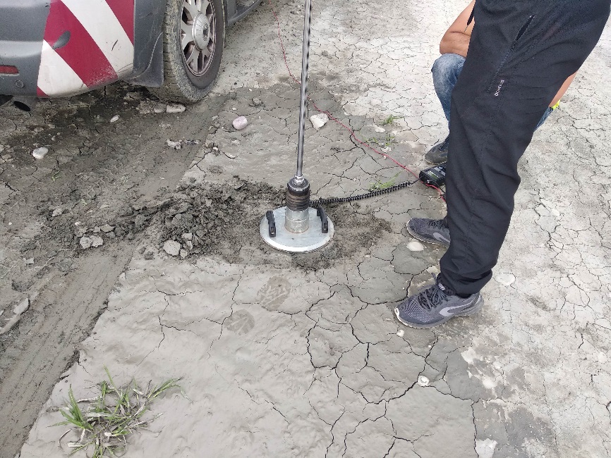
The light weight deflectometer (LWD), also known as the light falling weight deflectometer, light drop weight tester, and dynamic plate load test, is a hand portable device that was developed in Germany to measure the soil in situ: the results obtained by the tests are the LWD dynamic modulus. Typically, this modulus is used to evaluate the bearing capacity and subsoil degree of compaction. Thus it is suitable for compaction quality control of soil-surfaced roads, embankments and replacement fill. As a dynamic test, the device is suited, in particular, for coarse and mixed grained soils, and it’s perfect for the detection of the Runway/Taxiway strip.
Laser Profilometer
The Laser Profilometer is used for the survey of the pavement roughness, longitudinal and transverse profiles and the definition of the index IRI (International Roughness Index), measured in mm/m. The IRI is a standardized index that contains the information required to establish the regularity of a road surface, as defined by the World Bank Technical Paper No. 45. The irregularities of a pavement are the result of an infinite number of wavelengths that make up the longitudinal profile of a pavement. In the airport area the size of the wavelengths that affect the regularity are generally between 0.5 – 60 meters, with widths ranging from a few millimeters to several centimeters. The profilometer can detect the actual profile of the pavement in the XY coordinates (relative), where X is the distance measured by the odometer and Y represents the planimetric and elevation profiles of the runway. Generally the system is capable of storing the actual average profile every 100/200 mm of each section. The knowledge of the amplitude to short-wave (1 – 3.3 m), medium (3.3 m – 13 m) and long (13 m – 60 m) is very important to identify the cause of the irregularities. Where the irregularity is due to short wave is likely that the cause is to be found in the surface layers of the pavement (surface distresses), while the irregularities due to the long and medium wave may be due to problems of subsidence in the bottom layers. The software allows, through simulation, to analyze the results filtered to obtain the values of irregularities at the wavelengths desired. Since actual profile, the following parameters are estimated for sections of 20/25 m:
- IRI (International Roughness Index) averaged in mm/m;
- irregularities filtered to short waves from 1 to 3.3 m in mm/m;
- irregularities filtered to medium waves from 3.3 to 13 m;
- irregularities filtered to long waves from 13 to 60 m;
- simulation of a 3 m straightedge for calculating the maximum deflection, as required by ICAO standards;
- the maximum deflection on sections of 45 m and the number of irregularities that in this section exceed 20-30 mm as required by ICAO standards;
- Cross slope (%).
The equipment includes:
- various lasers to measure the cross slope for a width of about 3 meters and the longitudinal profile (IRI), with a sampling frequency of every 5 mm;
- N. 3 accelerometers and N. 2 high-precision gyroscopes;
- software for data processing for the determination of cross-slope, longitudinal profiles (IRI) irregularities for short, medium and long waves.
Survey Distress: PCI (Pavement Condition Index) analysis
The survey of the surface distress for rigid and flexible pavements is necessary to:
- Monitoring surface degradation and its evolution over time;
- Identify degraded areas that need emergency actions;
- Provide preventive maintenance and rehabilitation to prolong the service life of the pavement.
The RODECO Group has developed the ADE (Automated Distress Evaluation), an advanced technology for the automatic detection of surface distress.
The RODECO Videocar system collects images every meter, for a width of 4 meters, with high resolution cameras, so practically the survey is carried out in a continuous way.
All images are compressed before storing on onboard computer system. During the survey, cameras adjustment is provided in real time manually by a skill operator or throughout a dedicate software, to assure the high quality of each frame. Images location is provide by an accurate Distance Measurement Device (DMI) and a GPS technology.
All the images are collected in order to cover all the investigated pavements; after the analysis of the images, the main distresses will be detected and used to calculate the PCI index for each sample unit.
The post-processing software, used by our technicians, permits to evaluate the main distresses reported in the ASTM D5340-12 and ASTM D6433-18. The images are processed merging 5 file together: in this way, it’s possible to process about 20 m2 of pavement each time (the width of the 2 rear camera images is 4 m, and the height is 1 m). The method is semi-automatic because the operator can correct the results of the software, choosing directly on the main software mask the gravity, the extension and the quantity of each distress. The results is the PCI, a numerical index, ranging from 0 for a failed pavement to 100 for a pavement in optimal condition or new. PCI is divided into three classes:
The images are processed merging 5 file together: in this way, it’s possible to process about 20 m2 of pavement each time (the width of the 2 rear camera images is 4 m, and the height is 1 m). The method is semi-automatic because the operator can correct the results of the software, choosing directly on the main software mask the gravity, the extension and the quantity of each distress.
- 70 ≤ PCI < 100 good
- 55 < PCI < 70 fair
- PCI ≤ 55 poor
Ground Penetrating Radar (GPR) Surveys
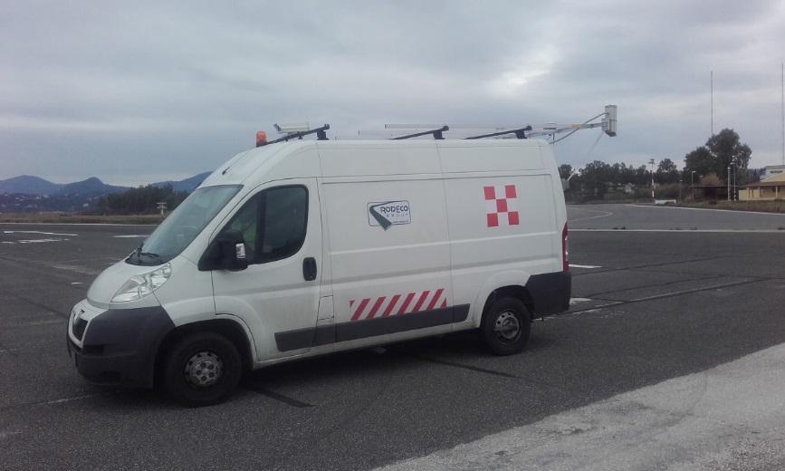
Through the use of GPR technology, it is possible to continuously detect the stratigraphy of the pavement and to estimate the thickness of the different layers. The output of the surveys consists of numerical tables and/or graphics that provide the thickness of the different layers of the existing pavement. The data obtained from the GPR surveys are used to process the HWD data and for the study of PMS. RODECO Group has a radar system equipped for the continuous survey of the stratigraphy of the airport pavements. The system may take up to 3 antennas operating between 200 MHz and 2 GHz. The antennas are installed on a vehicle properly equipped with the apparatus of reception, a computer process, a high-resolution color video and an odometer to measure the distances. The vehicle is able to continuously detect the stratigraphy of the airport pavements and in particular the thicknesses of the different layers, to a depth varying with the frequency of the antenna, 1 to 3 m. The collected data can be displayed on screen in real time or processed to produce tables and graphs. The results of investigations with the GPR are used to estimate the elastic moduli of different layers of the pavement as resulting from HWD tests. The GPR system uses radar technology to explore the layers of the pavement, measuring the time for reflection of electromagnetic waves sent from an antenna source.
Skid Resistance Surveys
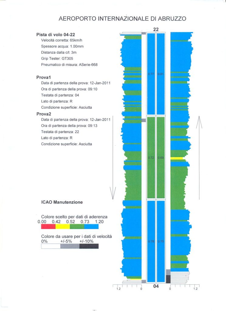
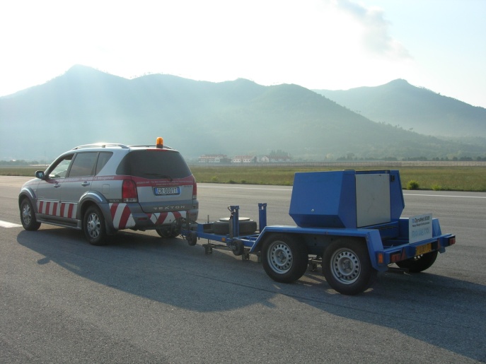
The skid data collection of pavements has a very important rule to assess the adequacy of air traffic safety level. In addition to the traditional static methods to evaluate the friction coefficient, such as the british pendulum friction tester, there are high-performance systems that can measure the friction by a moving vehicle properly equipped. With these measurement systems, skid resistance can be detected almost continuously, every 10 meter of pavement length. The GripTester, approved by ICAO, is a very simple device, consisting of a trailer towed to a vehicle; the trailer has two side wheels and a central wheel, braked during movement, used to measure the friction coefficient. The braked wheel is constantly sprinkled with water by a tank installed on the driving vehicle during the tests. The water flow is regulated with an electronic pump to ensure the desired thickness (eg. 1 mm of water) between the tire and pavement; this water thickness doesn’t depend of the speed measurement. During the trailer movement, two longitudinal strain gauges measure the strain “Fo” (which is opposed to the travel) and the vertical load “Fv”, given by the weight of the trailer; “Fv/Fo” ratio is the Grip Number. The strain gauges are connected to an electronic system that records data value of the friction coefficient measured every 10 meters on a onboard computer. The tests are performed with equipment Findlay Irvine – MK2 GripTester according to the requirements of the legislation (ICAO Annex 14 – Aerodromes Volume I – Aerodrome Design) at a speed of 65 and 95 km/h. Measurements are performed along 4 lines, at ± 3 and ± 6 meters from the runway centerline. According to the ICAO regulations, measures will be repeated for each path with two speeds: 65 and 95 km/h. Processed data can be provided in charts and graphics for every test point values, and the relative average values every third of the runway lenght, as required by ICAO standards, are reported.
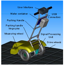
The Micro GripTester is a three-wheel manually pushed device which measures friction by the braked wheel, fixed slip principle. The device is known as a “Continuous” friction measuring equipment (CFME) as it measures continuously along the test path, rather than just taking a single spot reading. The device carries its own water supply and has an inbuilt water control system to maintain a known water film thickness where testing of the surface in wet condition is required. Its single measuring wheel, fitted with a special smooth tread tire made to an American Society for Testing and Materials (ASTM) standard, is mounted on an instrumented axle.
